Static Load Optimization
Learn how to apply forces, set constraints, and generate lightweight optimized designs with Vixiv AI’s static load optimization workflow.
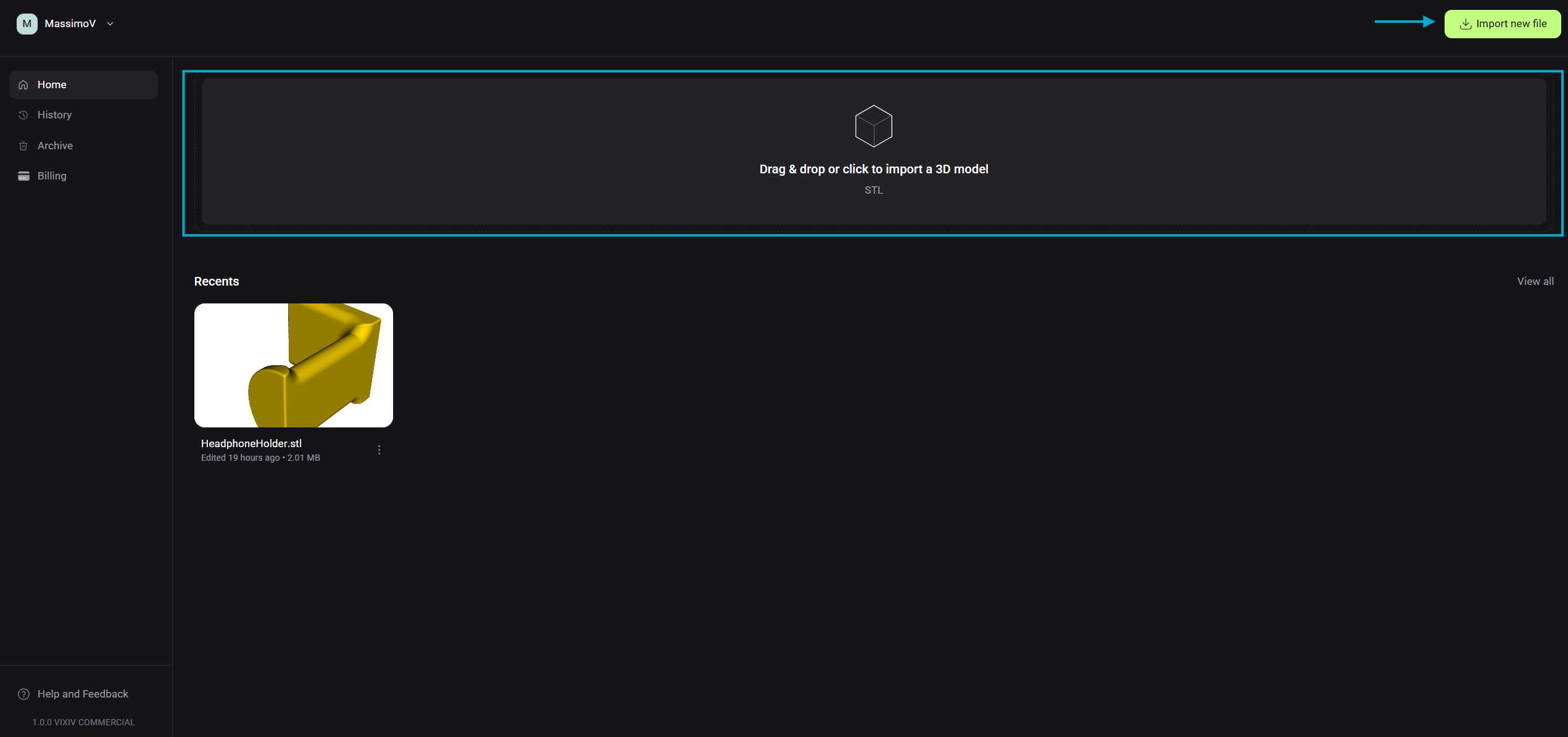
1. Import Your 3D Model to Vixiv AI
- From the Home Page, click “Drag & drop or click to import a 3D model” or use the “Import new file” button in the upper right.
- File format: must be an STL file.
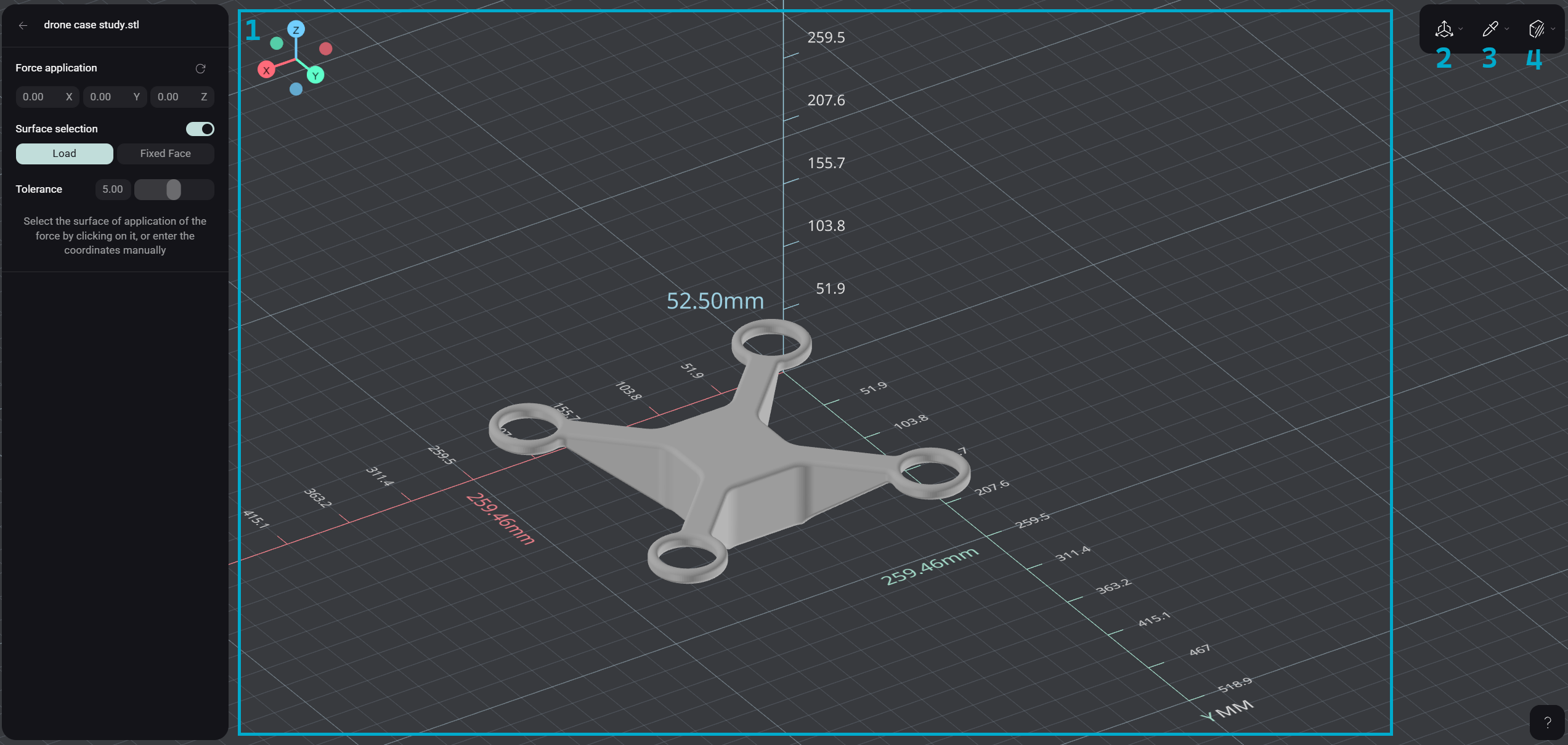
2. Explore the Optimization Workspace
Once your file is open, you’ll see it displayed in a 3D workspace with grid and dimensions.
- Navigation controls:
- Left-click + drag → rotate your part
- Scroll wheel → zoom in/out
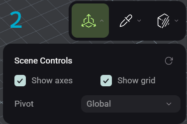
- Scene Visualization:
- Toggle axes and grid on/off
- Switch pivot axis (Global or Model)
- Reset view to default (⟳)
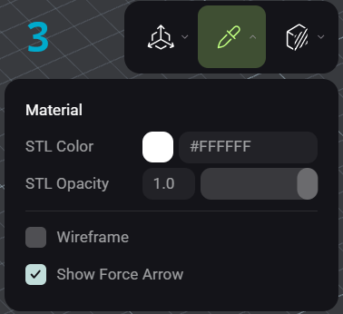
- Material Visualization:
- Adjust STL color and opacity
- Show/hide wireframe
- Show/hide force arrows
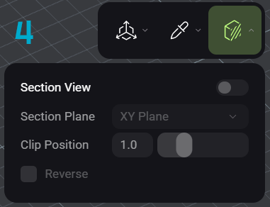
- Section View:
- Enable/disable section cut
- Choose a plane and clip position
- Reverse the section view direction
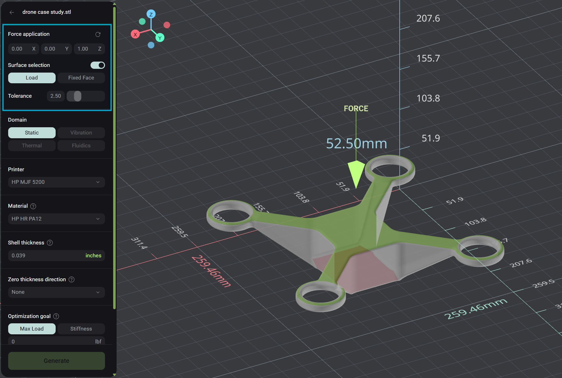
3. Apply Force and Constraints
Static load optimization requires selecting both a load surface and a fixed surface.
- Load (Green):
- In the upper left, select Load.
- Click on the surface where you want to apply force (highlights in green).
- Optional: specify a force direction. If left blank, the force is normal to the surface.
- Remove a load by clicking the same surface again.
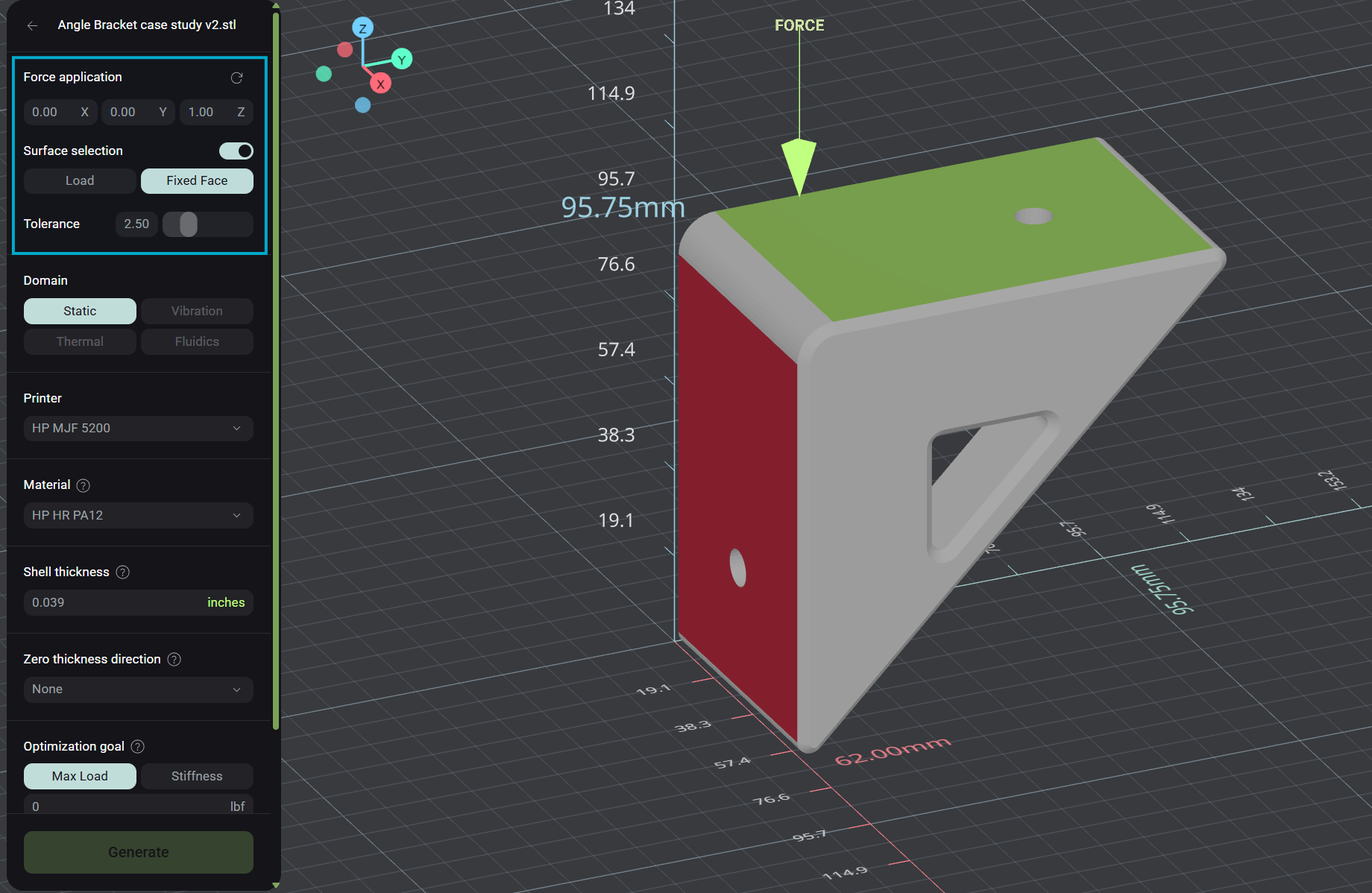
- Fixed Face (Red):
- In the upper left, select Fixed Face.
- Choose the surface that represents attachment (e.g., bottom surface on a floor, side of an angle bracket attached to a wall).
- Surface highlights in red.
- Remove by clicking again.
- Tolerance:
Adjust tolerance to capture more of a curved surface.- Low tolerance = fewer triangles selected
- High tolerance = more triangles included
4. Set Optimization Requirements
- Domain: Static loading (upcoming domains: Vibration, Thermal, Fluidics, Multi-physics).
- Printer: HP MJF 5200 (upcoming printers: FDM, SLA, and other manufacturing methods)
- Material: Currently trained on PA 12 (upcoming materials: more polymer materials, metallics)
- Shell Thickness: Default 1 mm (0.039 in). Maintains a perimeter “skin” for drilling or attachments. Toggle between SI and imperial units.
- Zero Thickness Direction: Allows powder removal (required for powder-based printers like MJF). Choose an axis or “None” for enclosed lattices.
- Optimization Goal: Optimize for Max Load or Stiffness.
- Currently supported loads: 0–10,000 lbf (0–44,482 N)
- Generated outputs will satisfy the inputed optimization goal
- Optimization Start Point: User defines start point of the voxel network
- Default: Voxel network will start at the center of mass of part
- Custom: Defined by coordinates with a purple indicator placed in the part prior to generation for visualization purposes
- Conformal Lattice: When enabled, the generated lattice within the part will reach the edges of the part. Full voxels will be placed on the interior of the part, with partial voxels filling out the remaining volume until it reaches the “edge” of the part. The “edge” of the part is bounded by the perimeter shape of the part and the user-selected shell thickness.
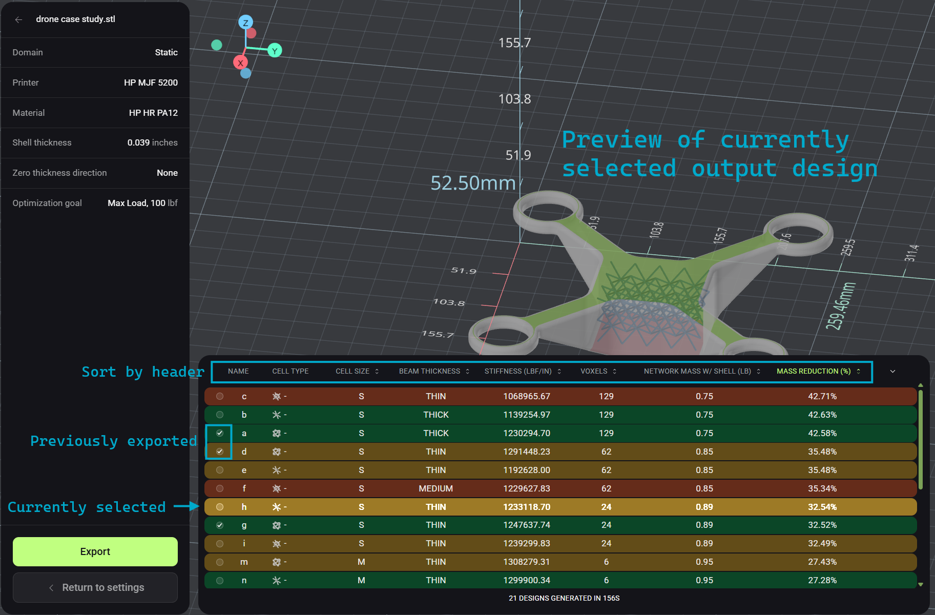
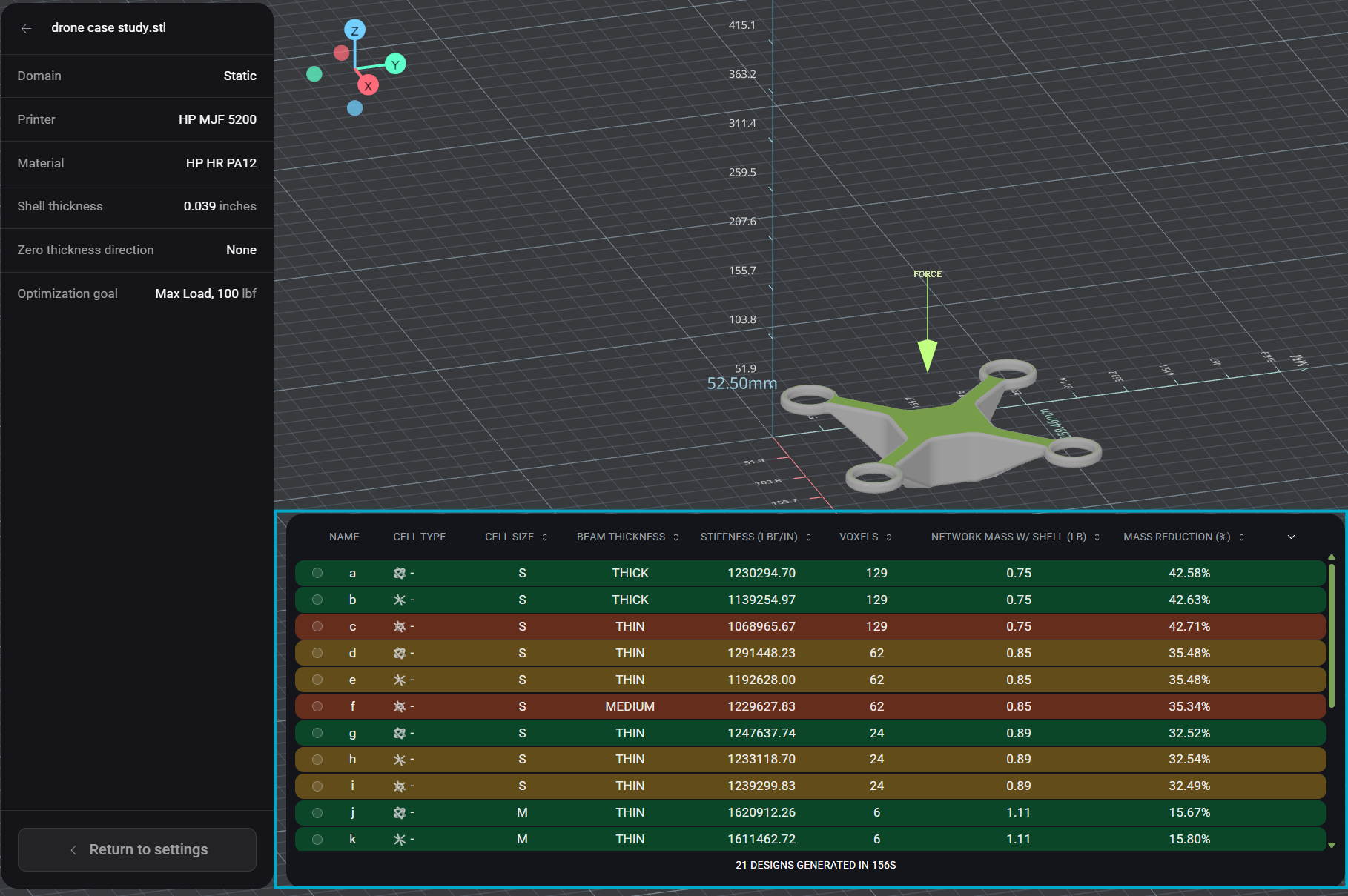
5. Generate a Design
Click Generate to start optimization. Vixiv AI will generate a table of up to 21 unique solutions that all satisfy optimization goal.
- Est time: ~10 minutes.
- There is no token cost if zero designs are generated.
- Table color code:
- Green → easiest to manufacture/unpack based on printer.
- Yellow → moderately challenging based on printer.
- Red → hardest to manufacture/unpack based on printer.
- Note: “Red” doesn’t mean bad — it may provide the best stiffness or mass reduction depending on your needs.
6. Review, Sort, and Export
- Sort designs by your priorities (mass reduction, stiffness, etc.)
- Preview output designs directly in Vixiv AI by selecting individual outputs.
- Est time: <1 minute per preview.
- Export your chosen design as an STL file (triangulated mesh).
- Est time: ~10 minutes per export.
- Outputs with checkmarks indicate previously exported outputs.
- Slice the exported file with your preferred slicer and print immediately.